02 / CHAPTER 05
Free-body diagrams
Turn a physical scene into a complete, auditable force model.
ANCHOR EQUATION
Free-body balance
In symbols: ΣFx = max, ΣFy = may
Resolve one vector law into axes that match the geometry.
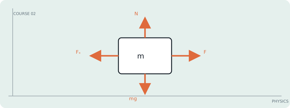
A free-body diagram is a model boundary
The diagram is a compressed statement of what crosses the chosen system boundary as a force. It is not a picture of every object in the scene and should not include forces the system exerts on other bodies.
From scene to equations
Choose the body, draw it as a point or box, and attach one arrow per external interaction: gravity, contact, tension, drag, or applied force. Resolve arrows into axes, then write ΣFₓ = maₓ and ΣFᵧ = maᵧ. The drawing earns its keep by making omitted and duplicated interactions visible.
For a 4 kg sled on a 20° incline, weight has components mg sin20° = 13.4 N downhill and mg cos20° = 36.8 N into the plane. With no perpendicular acceleration, N = 36.8 N; with μ_k = 0.10, friction = 3.68 N uphill, leaving 9.7 N downhill and a = 2.43 m/s².
A force diagram depends on the system
The tension in a rope is an external force for the sled but internal if sled plus rope are the system. A normal force need not equal mg on an incline or during vertical acceleration; it is whatever the perpendicular balance requires.
Work it: Draw and solve the free-body diagram for a 6 kg elevator accelerating upward at 1.2 m/s². Then explain why the cable tension exceeds the elevator’s weight.