04 / CHAPTER 12
Rotation studio: impeller and shaft
Estimate torque, inertia, and startup behavior for a pump assembly.
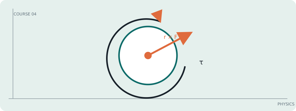
ANCHOR EQUATION
Rotational dynamics
In symbols: τ = Iα
The rotational counterpart of Newton’s second law.
An impeller needs torque before it needs speed
A pump shaft first accelerates the rotor and water, then supplies steady torque against hydraulic and mechanical resistance. Startup behavior depends on inertia; operating power depends on torque times angular speed.
Write the rotor equation
For a shaft with total rotational inertia I, Στ = Iα. If motor torque τ_m opposes load torque τ_L, α = (τ_m − τ_L)/I. Once speed is steady, α = 0 and τ_m = τ_L; the required mechanical power is P = τ_Lω.
If I = 0.020 kg·m², motor torque is 1.2 N·m, and load torque is 0.7 N·m, α = 0.5/0.020 = 25 rad/s². Reaching 100 rad/s from rest takes 4.0 s in the ideal constant-torque model; steady output power is 70 W.
Fluid load is not usually constant
Pump torque varies with flow, speed, viscosity, and blockage. An impeller model with constant load is a local approximation; compare it with measured current or a manufacturer torque curve.
Work it: Estimate startup time for I = 0.05 kg·m², net torque 0.8 N·m, and target 120 rad/s. Then compute shaft power if the load torque at speed is 0.8 N·m.